Oakland MallBuilding Automation
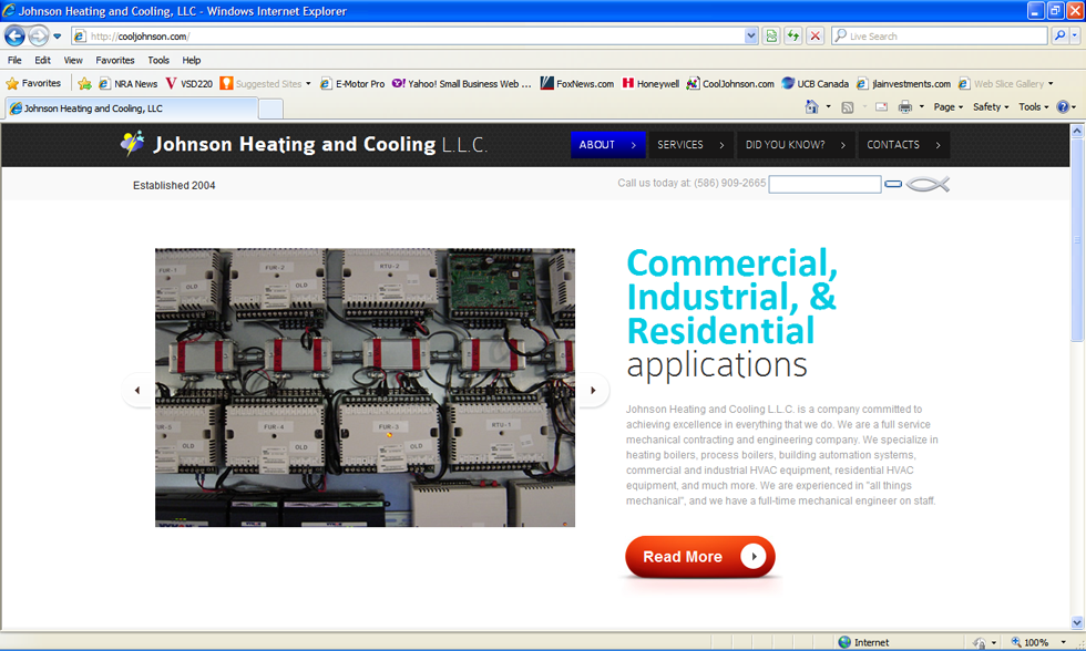
In 2013 Johnson Heating and Cooling L.L.C. was contracted to install a building automation system that would control the mechanical systems for the Oakland Mall, located in Troy, Michigan.
BAS Page
Building Automation System User Manual
The Oakland Mall
Building Automation System- Getting Started
To effectively operate your DDC system it is important to understand how your system is set up and how it operates. Your system is composed of five groups of different physical components. Also, your system has two different groups of components in which application specific custom programming resides. For starters, we’ll look at each of the five groups of physical components and discuss their functions.
The Server
The server is, essentially, a computer/web server in where most of the system’s custom programming and unit control resides. Typically there is only one server per structure. The Oakland Mall has five servers, all connected to one another via a fiber optic TCP/IP network. The primary server is what the end user interacts with when he logs into the system. The primary server is responsible for displaying the automated web based graphics. Both the primary and secondary servers upload the values from the controllers, download values/commands to the controllers, and process/perform the sending of alarms. Your primary server is located in the primary riser room. The secondary servers are located in RTU2-NM, RTU1-GC, RTU2-GC, and RTU2-FC.
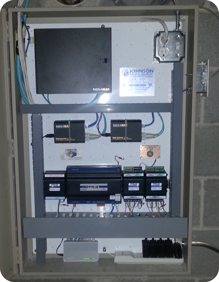
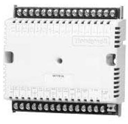
The Controllers
The controllers are devices that command the units’ (i.e. V.A.V. or roof-top unit) operations, retain sensor and wall module values, and communicate with the server. Each unit has one controller, and it is typically located in or near the unit. Essential custom programming for the proper unit operation is located within each controller. Because some of the values/commands that the controllers need come from the server, the controllers’ operation changes when communication to or from the server is interrupted (reference the “Troubleshooting” section of this guide for more information on what happens when the communication between the server and a controller fails). The unit controller is solely responsible for commanding its unit, however its decision to make a certain command may be based on an outside parameter coming from the server or coming from another controller.
The Digital Wall Modules
The digital wall modules look similar to thermostats, and are located in the area that it’s unit conditions. This building does not use “digital wall modules”, but may in the future. The current system at the Mall uses a combination of sensors to determine space temperature. The digital wall modules do not make any decisions; their only functions are to provide values to the unit’s controller, to display the current space temperature, to display the wall module set point on its display, and provide a means for the occupants of the space to put the unit into override. The digital wall modules at each location have one adjustable temperature set point wheel, and one LCD display. The buttons on the wall module serve no purpose and do not function.
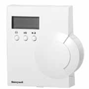
Turning the wall module set point wheel sets the occupancy state to occupied, and sets the active space temperature set point to the adjustable value that is displayed on the LCD. This value is called the “wall module set point” and can be viewed via the computer system under the specific unit’s page. The wall module set point can also be viewed by turning the wall module wheel one click, and can be changed by continuing to turn the wall module wheel. Turning the wall module wheel one click displays the wall module value, but does not put the space into override. The override function of the wall module can be disabled on its corresponding web page. The Mall has no digital wall modules installed; however, the system components at the Mall are compatible with these wall modules, so we can always add them later.
The Sensors
The various sensors in this DDC system provide values to the units’ controllers.
The Bus Line
The bus line is a two (and sometimes four) conductor wire that links all of the controllers to the server and to each other. All communication between the server and the controllers and between individual controllers goes through the bus line. If the bus line fails at a specific point, then all communication that would normally travel through that point will fail.
The two “Brains” of each Unit
Each unit (V.A.V. box or roof-top unit) has two “programmable logic controllers” that control it, and they both work together to decide what commands to make. The two brains that each unit has are the server and the controller.
The controller is only able to function in certain ways. Each controller has an application specific custom program embedded in its memory. The embedded program in the controller was designed only to perform in a very specific manner, but as we typically do on every project, we’ve manipulated the controller to perform in the most efficient manner. The programs in the controllers are manipulated in such a way (by the program in the server) so that all of the desired system operations could be achieved, while at the same time ensuring the highest level of redundancy in the event of certain system components failing. The controller is set up so that it will control the unit with or without the server, however, without the server, the system is severely crippled. Simply stated, the program in the server’s memory manipulates the programs in the controllers.
One example of the manipulation that we’ve performed is the use of global economization. The Honeywell XL-10B’s used on this project are not capable of receiving a global outdoor humidity or a global outdoor air temperature value. Presumably, Honeywell designed the controllers in this way so that a customer would need to purchase an outdoor air temperature and an outdoor air humidity sensor for each roof-top unit. In addition to an increased project cost, due to purchasing multiple outdoor air temperature and outdoor air humidity sensors (one for each unit), there would be issues with individual sensors failing over time, so the legacy costs associated with the conventional Honeywell design would be undesirable, all be it economical, due to energy savings (when compared to a system without the sensors necessary for economization). The beautiful thing about our system is that we use global enthalpy via manipulating the controllers in the way that we have, which is unconventional, to say the least. One outdoor air humidity sensor and one outdoor air temperature sensor, per site, mean that only one outdoor air temperature sensor and only one outdoor air humidity sensor can go bad per site. In addition to low legacy costs due to equipment replacement, the time needed to verify and calibrate the, all important, outdoor air temperature and humidity sensors is reduced, because there is only one of each, per site, instead of 27 of each per site. This configuration offers the lowest possible legacy costs of any system.
We achieved global economization control via programming in the servers. The servers receive the outdoor air temperature, the outdoor air humidity, and the space temperature (which is calculated for each individual unit), and then the readings are put into economization programs that calculate if it is more or less profitable to bring in outdoor air, or to recirculate indoor air. The programs take into account the cost difference between utilizing blower motors and exhaust fans or utilizing mechanical cooling (compressors & condenser fan motors) and makes its decision accordingly. The enthalpy program doesn’t simply compare outdoor air temp with indoor air temp, and outdoor air humidity with the calculated indoor air humidity, and make its decision according to the lowest enthalpy, but it actually, passively, considers the equipment operation costs compared to the BTU transfer rates and goes with the lowest number. The program functions better than if a man was standing in a control room 24/7, with a calculator, crunching the numbers on enthalpy and energy consumption per BTU of heat transfer, and then opening and closing dampers, turning on and off exhaust fans, etc, because the computer program has virtually no delay, it can perform hundreds of calculations and actions per second, and it doesn’t ever add wrong. It’s a safe bet that the new system is head and shoulders above the previous system, not only because of it’s use of very accurate economization programming, but also because the new system utilizes the building’s existing exhaust fans to “super-charge” the economization of the roof-top units, which makes economization about five times more profitable- which is huge!
Due to the incredible complexity of the economization programs in the system, the options to enable and disable the economization program is all in the code and can not be accessed by a non-programmer. Besides the point that the economization program is buried in the code of five servers and can not be adjusted, we feel confident that any changes to the code would only have an adverse effect on the system, so no changes should ever need to be made to the economization programming.
Building Automation System- Operating the Program
All of the programs in every device at your building were specifically made for your building, with the end user in mind, so navigating through the system and changing values should be fairly easy. The system was designed for several purposes: To provide centralized remote consoles (any computer or smart device with internet access) to change settings and monitor the HVAC systems for the sake of energy conservation and convenience, to provide a means to diagnose or expedite the diagnosis of mechanical failures, and to provide a means of sending out alarms in the event of a HVAC component failure or poor operation.
Logging on to the System
To log on to the HVAC system you must have a computer with internet access, a mouse or some other pointing device, and a keyboard. Go to the following web site www.CoolJohnson.com . Enter the site, scroll to the bottom of the home page and locate the “Quick Links” column of links. Click on the link with the abbreviations of your building’s name (Oakland Mall). Enter your username and password, and then you’re in.
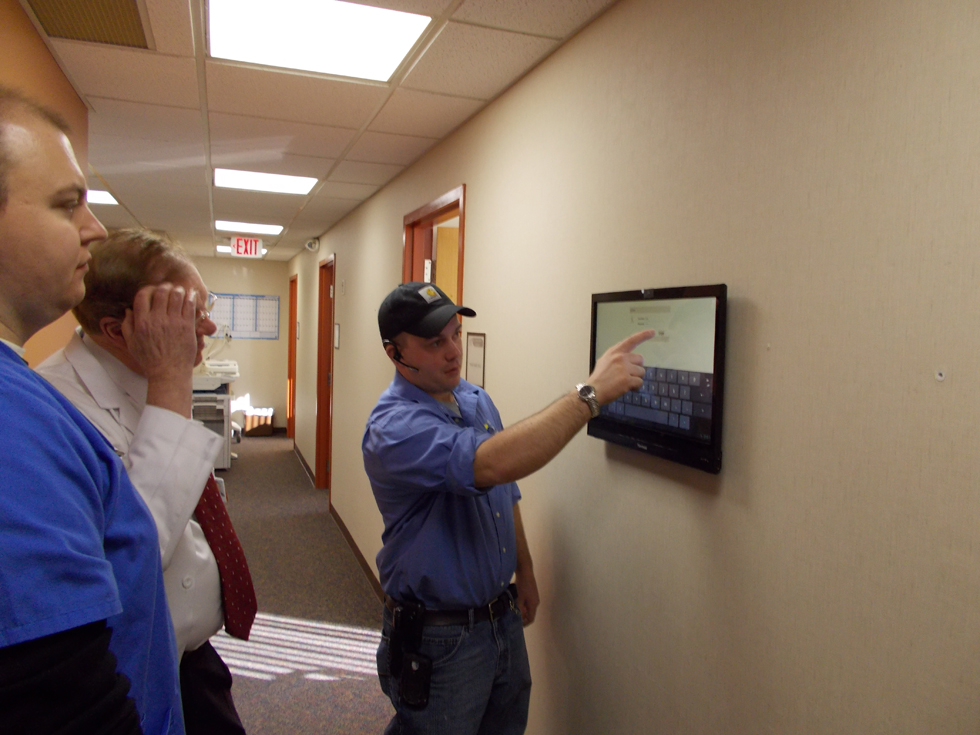
Smart Phones, Tablets, and Touchscreen Interfaces
While designing the graphical user interface for this system, we went the extra mile and fully integrated and optimized the interface for mobile devices. On previous projects, we have even gone so far as to fix an interface problem in the Honeywell software itself, so that the interface could be more easily operated from any mobile device. If your building has a touch-screen display interface, you will notice that it functions in the same way as an Android phone. All of the rules and principles of system operation are the same, and this display has been added for your convenience.
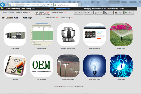
Navigation
Navigating though the system is very easy. It is set up just like a common web page, and all one needs to do is point and click. The only pages that do not have return links (that is, the only pages that are dead-ends) are the schedules. When one wishes to return from the schedule page to the previous page, all one needs to do is click on the back arrow of his web browser. Once you log into the system you will see the primary navigation page. From the primary navigation page, one is able to navigate to the areas of the program to which his security level allows him to go to simply by clicking on the link or picture.
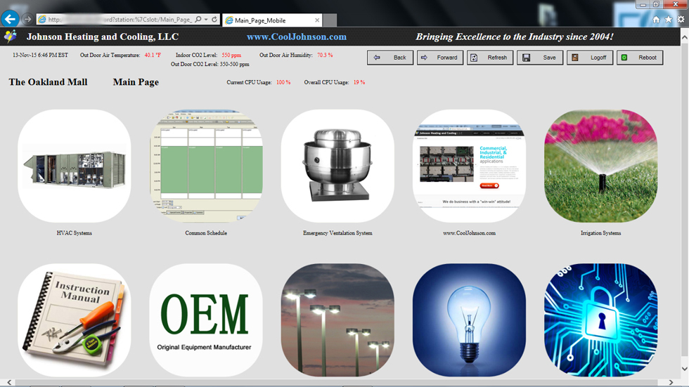
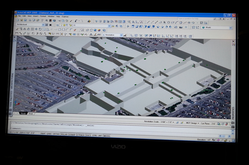
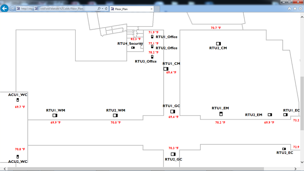
Please note that clicking on the temperature value on the 3-D graphic or map will take you to the equipment that conditions that space.
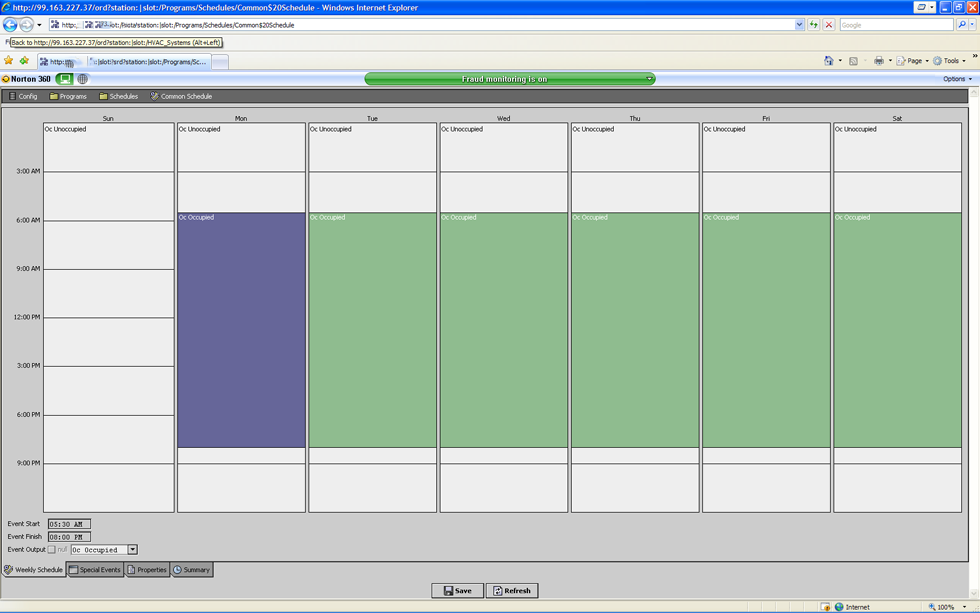
This is a picture of a schedule:
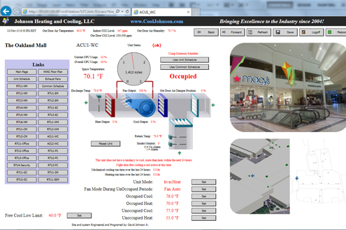
The Program Infrastructure
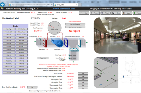
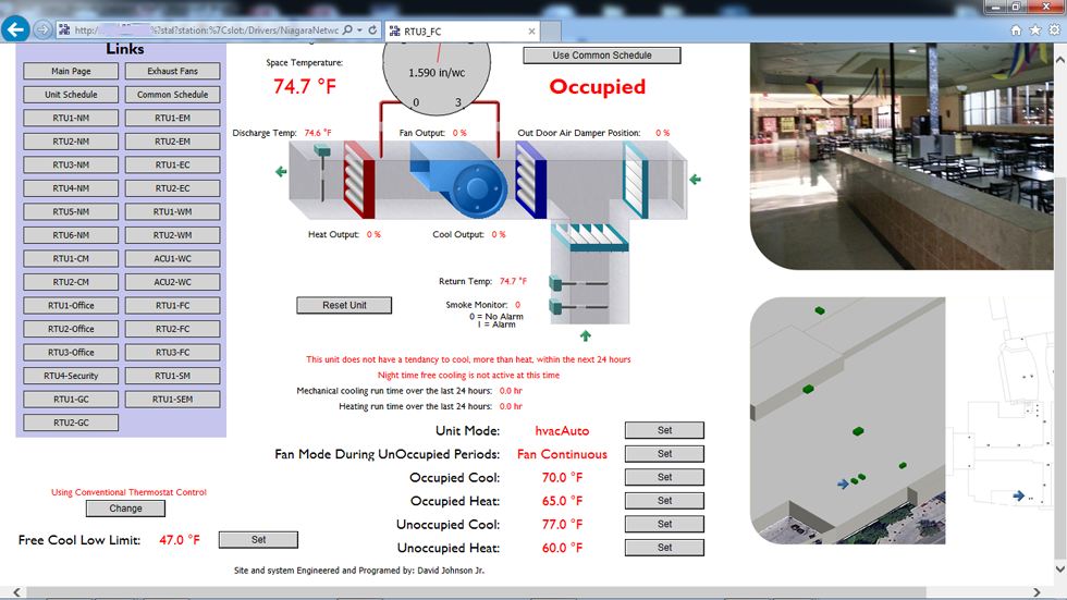
You will notice that many of the graphics look the same from page to page, so it is important to verify that you are actually on the correct unit’s page before making changes or determinations. In the upper left corner of each of the unit pages, there is a name (i.e. “Roof-top Unit”, “Furnace”, “VAV”, etc.) and a number that denotes what unit page you are actually on. When appropriate, the different pages will have 3-D pictures with the correlating conditioned space indicated by a blue background. Please remember that air migrates, so in some places obtaining two different space temperatures in close quarters may be difficult.
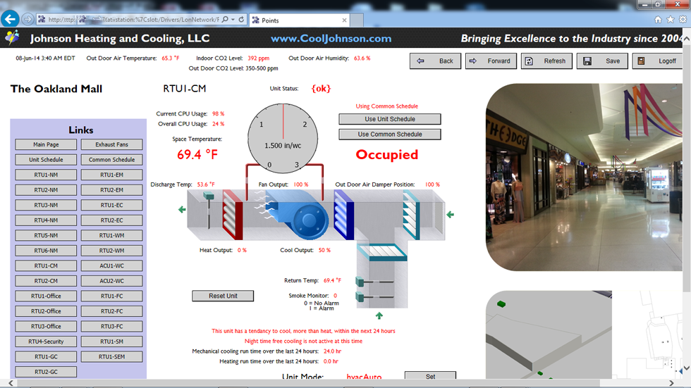
It is very obvious how to change values. Just point and click. Since this program was created with the end-user in mind, almost all of the values and set points displayed are very easy to understand, however there are still a few values and functions that may need some explanation, and they are as follows:
Fan Mode-The fan mode setting determines the operation of the fan. When the fan mode is in the auto state the fan turns on when the unit turns on the heating or the cooling. Because of air stratification concerns, the fan runs continuously during occupied periods. During unoccupied periods the roof-top units will run the fans at the top of every hour for five minute increments. When the fan is set in the continuous mode, the fan runs all the time.
Space Temperature- The space temperature value denotes the temperature of the air in the area that the unit conditions.
Effective Setpoint-The value at which the unit engages the denoted action. For example, if the effective set point is 68oF for “hvacheat”, then the controller will energize the heating circuit when the space temperature is below 68oF, but if the space temperature is at 68.3oF the controller will not energize the heating circuit. This building does not use “effective set point”, but may if wall modules are added in the future.
Occupied CoolingSet point- The controller will try to maintain a temperature below the occupied cooling set point temperature, during occupied times.
Occupied HeatingSet point- The controller will try to maintain a temperature above the occupied heating set point temperature, during occupied times.
Wall Module Setpoint- The wall module set point is the value which replaces the occupied space temperature set point when the controller is in bypass mode. Controllers that are slave controllers receive their wall module set point from their master controller. This building does not use “wall module set point”, but may if wall modules are added in the future.
Wall Module Override Time-This value sets the time that the controller will remain in the override state once the override is activated. This building does not use “wall module override time”, but may if wall modules are added in the future.
Use Common Occupancy Schedule option-When this value is selected, the controller will get its occupancy values from the common schedule. When this option is not selected, the controller will get its occupancy values from its own (dedicated to only that controller) unit schedule.
Enable Wall Module Override-When this option is enabled, the set point temperature will be changed to match the wall module set point when the controller’s wall module set point temperature is changed. When this override is enabled, the set point temperature will be changed to match the wall module set point temperature when the wall module set point temperature is changed. This building does not use “enable wall module override”, but may if wall modules are added in the future.
Unoccupied Heating Set point-When the space temperature is less than this value, and the occupancy state of the controller is unoccupied, the controller will energize the heat circuit.
Unoccupied Cooling Set point- When the space temperature is greater than this value, and the occupancy state of the controller is unoccupied, the controller will energize the cool circuit.
Equipment with two options for control
We have been asked to provide for two means of control for several HVAC units. The units that currently have the option for two different types of control are as follows: RTU1-Office, RTU2-Office, RTU3-Office, RTU4-Security, RTU2-FC, and RTU3-FC. Those units can either use conventional thermostats or building automation system control. The option to change the equipment’s control is located in the lower left hand corner of the equipment’s unit page.
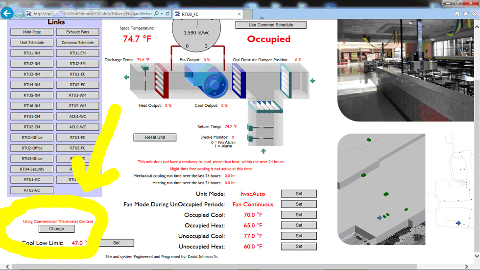
We feel that it is unnecessary to utilize two forms of control, i.e. the thermostats and the building automation system; however, the option to use thermostat control does offer a very small level of additional redundancy. We were asked to incorporate the thermostat control into the new system, so we did. The benefit of the building automation control system is that we are able to incorporate night time testing features into the equipments’ programming, which can run the equipment during an unoccupied time, say 3am, to test the equipments’ operation. Therefore, if the equipment does have a problem, we can know about the issue first thing in the morning. Also, if the equipment is still operational, but is operating inefficiently, we can also know about the matter prior to the space losing its air conditioning.
Building Automation System- Specific Building Considerations
This is undoubtedly the most important section of this users’ manual. Please take the time to understand the following, and feel free to ask questions if it is necessary.
How do you save customer money when their HVAC roof-top units run almost continuously, because of a high heat load and because of an enormous amount of thermal capacity in the structure? The answer is with outdoor air. During the hottest months in the summer, typical night time lows are at about 65 degrees. The coldest time of the day is just after dawn, but from a practical stand point, one could say that between 4am and 6am is the coldest part of the day. The system at the Oakland Mall is state of the art, because it utilizes the Mall’s existing equipment and a sophisticated program which uses the equipment to proactively ventilate the structure with cool air prior to the next hot day. The idea is to drop the building’s space temperature a few degrees via RTU’s and exhaust fans (only when the out door air and humidity values are favorable) and then to let the building warm up a few degrees before turning on mechanical cooling. The math makes sense! Fans are much less expensive to operate than mechanical cooling, and ventilating the building alleviates any need to do so during inopportune times, because of high CO2 levels.
The trick to operating the system effectively is easy to miss. Because the system/program requires a high and low limit (a high limit which turns on the free cooling, and the low limit which stops the free cooling, so that the heat doesn’t come on), and because the night time free cooling activates between 4am and 6am, which is just before the system will go into the occupied state, the program uses it’s occupied heating and occupied cooling set points to determine the limits for the night time free cooling period. The following formula is used to control night time free cooling:
If occupied cooling set point = OC, and
If occupied heating set point= OH, and
If the night time free cooling set point = NTFC, and
If the outdoor air and humidity levels are suitable, compared to that of the indoor air, and
If the equipment is likely to need to cool during the next 24 hour period, then
NTFC= OC - (OC-OH) * 0.67
For example:
If the occupied cooling set point (or OC)= 70, and
If the occupied heating set point (or OH) =65, then
NTFC= 70 – (70-65) * 0.67
NTFC= 70 – 5 * 0.67
NTFC= 70- 3.35
NTFC= 66.65
The night time free cooling set point acts like an economizer on first stage cool, when outdoor ambient conditions are more suitable for using outdoor air, then for using mechanical cooling, to cool. For the layman: if it’s cold outside, sometimes it makes more sense to simply run the fans, to bring in outside air, than it does to run the compressor to cool the indoor air, and it make more sense to do either when outdoor air temperatures are cooler.
The excellent thing about the free night time cooling program is that it not only uses an enthalpy program to very accurately determine the most efficient course of cooling (if outdoor air temp/humidity is not suitable, then the program does not run), but it also lowers the occupied set point in the structure, it utilizes the building’s exhaust fans (which makes the roof top units about five times more effective at economization), and it also allows for virtually no need to ventilate the structure, due to indoor air quality concerns, because it does a complete air change a few times a day.
The night time free cooling program is likely to offer the mall a very short term ROI (with the largest savings in the fall and spring times), for the entire building automation system (and we make absolutely no guarantees to this effect), but only if the set points and program are properly adjusted. It’s very important to maintain at least a five degree spread between the occupied cooling, and the occupied heating set points. If you are the system operator, make sure that you understand the equation above, and make sure that you know that formula inside and out.
Equally important to maintaining proper settings on the new building automation system is that the equipment be properly maintained. The program does no good if the outdoor air dampers do not function and the fans are offline. Units with low refrigerant charges will cause extremely high electricity consumption, and so much so that while the benefit of the night time free cooling program will exist, it may not even be realized, if the equipment doesn’t function well. If a service man physically jumps out the heating circuit on one or several roof top units, with electric heat, (as was done by others, just prior to the installation of the new building automation system) it will appear as though the new system is actually increasing the energy consumption of the structure.
Air migration will be an unavoidable issue in any building with multiple temperature controllers in an open space. Keeping space temperature set point values at the same value (i.e. 68 degrees F throughout) will reduce energy bills and eliminate hot and cold spots though-out the building.
User error is usually a common problem. Please take the time to understand this system and the basic principles of thermodynamics. Read this manual, and ask questions. Remember to use the unoccupied setting, because turning the equipment off at night and on holidays saves energy and money. Good practice, for the person who maintains this system, is to check the system settings on a regular basis, even if no changes need to be made.
Building Automation System- Troubleshooting
For the most part, this is a “for your information” section of this guide, but it may become useful if anything in the system breaks down (and everything mechanical and electromechanical does break down). If there is a problem with your system, 99% of the time we will be the first to know. Because of the alarm programs built into your system, most issues will probably be resolved before you are ever inconvenienced or uncomfortable (if we are the servicing contractor). First off, if there is a problem with the system give us a call at (586) 909-2665. The following will tell you how to respond to a given situation.
The Connection to the System Fails-When you’re not able to connect to the system, probably one of two things have happened, either the internet connection has failed, or the server has failed. As long as the server has not failed the system will continue to operate according to the last values entered into the system. If the server has failed, than the unit controllers will maintain the settings that they had when the server failed. We are capable of reprogramming controllers in a matter of minutes, even if a server has failed, so there is no need to be concerned about the system’s robustness.
A Unit is Malfunctioning- If a unit is acting abnormal, please call us at: (586)909-2665. Your comfort and safety is very important to us. Note: this system is very reliable, and usually we will know of any issues before you do, if we are the servicing contractor.
Building Automation System- Warranty Terms and Conditions
Certain warranty benefits have been extended to the customer as part of our contract; however there are certain terms and conditions which must be followed in order for the warranty to remain valid. This manual does not serve as any form of legal document and is not intended to, in any way, alter or change any contractual agreement made between Johnson Heating and Cooling, LLC and the customer. The following is intended only to provide a brief guide of some things that we deem important to mention, concerning the warranty.
There are seven boxes that may not be opened at the mall, for the term of the warranty period, without prior written approval from David Johnson. Those boxes contain servers, fiber optic network components, and controls. The boxes that may not be opened are the five steal server boxes and the two steel emergency exhaust system relay boxes, located in the primary riser room, RTU2-NM, RTU1-GC, RTU2-GC, RTU2-FC, and under the stairs in the maintenance area (behind the security offices), respectively. Each of the boxes that may not be opened are not to be opened by any person for the term of the warranty period, because if there are any problems requiring access to those boxes, then those issues will almost certainly be warranty issues. In addition to our concerns about other’s adversely affecting the system, we are concerned about the safety of the occupants of the mall. Several of the boxes that may not be opened are alarmed, so we will know if our equipment is tampered with during the warranty period.
If the customer desires to open one of our boxes and maintain his warranty, he must first obtain written and verbal permission from David Johnson Jr. (Johnson Heating and Cooling, LLC, owner). We are not unreasonable, so if for some strange reason access to the boxes is needed, we are always inclined to work with our customers in the effort to maintain good relationships. The boxes may be easily opened, in the event of an emergency, and after written permission has been given by David Johnson, by simply pulling on the cabinet door. About 25 pounds of force is all that is needed to open the cabinet doors, when the lock is closed. The metal on the locking mechanism will bend, and can be easily bent back into position afterwards, with no damage done. If the box has an alarm installed, then we will know that the box has been tampered with, and if we have not been notified prior to the opening of the box (and given our consent) then the warranty extended in our contract may be affected or made void, at our discretion.
In addition to the requirement that none of the steel boxes be opened, it is also forbidden for anyone to tamper with the programming of any part of the system for the period of the warranty. Controller programming (there is a controller or server located in each HVAC roof-top unit) can be accessed via the LON-bus jack on the lower right hand corner of each controller, however if anyone even plugs anything into any of the LON-bus jacks, on any of the controllers, the warranty is null and void. There should be no reason for anyone to change any of the programming, in any part of the system that we’ve installed at the mall. There are aspects of the programming which may be adversely and severely affected by any change to any part of the system’s programming, no matter how seemingly inconsequential the changes are.
No controllers, sensors, or any part or component of the system may be moved, removed, rewired, or in any other way changed, without written permission from David Johnson, prior to any changes being made. Any such changes to any part of the system may affect or void the warranty; and that at the discretion of Johnson Heating and Cooling, LLC.
Building Automation System- Usernames and Passwords
Usernames and passwords are case sensitive and can be traced, so keep your username and password to yourself. A record of any activity on the server is created each time anything is done on the server. If a set point is changed, a record that indicates who changed the value, what the value was changed to, and when the change was made, is created. It is the responsibility of the users to ensure that usernames and passwords are only given to responsible people. Johnson Heating and Cooling, LLC can make changes to any usernames and passwords. To make changes to the log in credentials for your structure, e-mail us, detailing the changes requested, and then call us to verify that we have received your e-mail.
Based on who you are your access to certain parts of the system may be restricted. For example, the people upstairs cannot modify the set points downstairs. Like-wise, access to the roof-top equipment set points is restricted to Johnson Heating and Cooling, LLC, the building owner, and his representative.
These items and drawings are the sole property of Johnson Heating & Cooling LLC
No copies may be made without the express written permission of David Johnson.
Johnson Heating & Cooling LLC
Copyright, All Rights Reserved. 2014